Spring Sale Special Limited Time 70% Discount Offer - Ends in 0d 00h 00m 00s - Coupon code: buysanta

Exact2Pass Menu

Implementing and Administering Cisco Solutions (200-301 CCNA) v1.1

Navigating Modern Infrastructure: Why Hands-On Network Logic Trumps Static Memory Dumps

We have coached hundreds of junior systems technicians, desktop support specialists, and aspiring cloud infrastructure engineers through this foundational Cisco milestone. Let's look closely at the modern data center training landscape. The professionals who stumble on this updated v1.1 routing and switching evaluation are almost always those who relied on low-tier test pools—those flat, context-stripped answer repositories floating around public IT forums. Those static, unverified materials simply cannot prepare you for real-world interface configurations or the intricate packet-level troubleshooting tested on the real exam. At Exact2Pass, our approach targets the underlying structural logic, software-defined fabrics, and algorithmic execution patterns of the active Cisco IOS ecosystem instead. Our 200-301 CCNA exam prep delivers comprehensive programmatic breakdowns for every routing table preference and secure wireless access query. You will master actual core switching parameters instead of leaning on short-sighted memorization shortcuts. We map out Rapid PVST+ root bridge elections, VLSM IP allocation boundaries, single-area OSPFv2 neighbor adjacencies, and programmatic API authorization mechanisms step by step. Our learning material is built from the ground up by active network engineering architects who optimize enterprise corporate infrastructure daily. Because of that, we completely avoid mindless, repetitive question-and-answer lists. Instead, our workspace functions as an active training simulation that forces you to evaluate subnet hierarchies, traffic prioritization metrics, and software automation scripts like a seasoned system lead. You will learn the exact reason why a specific VLAN access rule or access control list configuration succeeds or breaks context under production constraints. That is how you build real confidence before logging into the official Pearson VUE and OnVUE testing environment. Our adaptive training software develops genuine technical expertise that transfers perfectly to production engineering sprints, helping you pass on your very first try.

Question # 181

Which two components are needed to create an Ansible script that configures a VLAN on a switch? (Choose two.)

A.

cookbook

B.

task

C.

playbook

D.

model

E.

recipe

Question # 182

Which statement correctly compares traditional networks and controller-based networks?

A.

Only traditional networks offer a centralized control plane

B.

Only traditional networks natively support centralized management

C.

Traditional and controller-based networks abstract policies from device configurations

D.

Only controller-based networks decouple the control plane and the data plane

Question # 183

Refer to the exhibit.

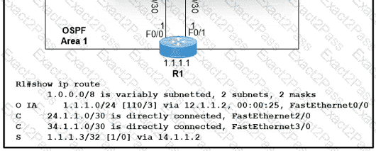
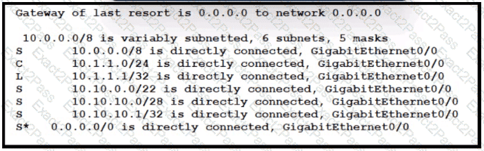
Which route type does the routing protocol Code D represent in the output?

A.

internal BGP route

B.

/24 route of a locally configured IP

C.

statically assigned route

D.

route learned through EIGRP

Question # 184

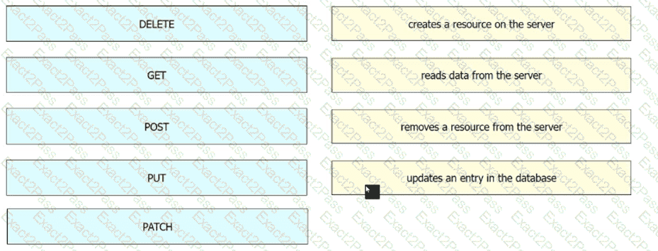
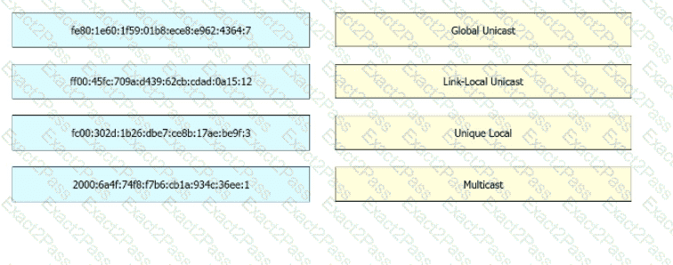
Drag and drop the application protocols from the left onto the transport protocols that it uses on the right

Question # 185

What does physical access control regulate?

A.

access to specific networks based on business function

B.

access to servers to prevent malicious activity

C.

access to computer networks and file systems

D.

access to networking equipment and facilities

Question # 186

IP connectivity and OSPF are preconfigured on all devices where necessary. Do not make any changes to the IP addressing or OSPF. The company policy uses connected interfaces and next hops when configuring static routes except for load balancing or redundancy without floating static. Connectivity must be established between subnet 172.20.20.128/25 on the Internet and the LAN at 192.168.0.0/24 connected to SW1:

1. Configure reachability to the switch SW1 LAN subnet in router R2.

2. Configure default reachability to the Internet subnet in router R1.

3. Configure a single static route in router R2 to reach to the Internet subnet considering both redundant links between routers R1 and R2. A default route is NOT allowed in router R2.

4. Configure a static route in router R1 toward the switch SW1 LAN subnet where the primary link must be through Ethernet0/1. and the backup link must be through Ethernet0/2 using a floating route. Use the minimal administrative distance value when required.

Question # 187

IP connectivity between the three routers is configured. OSPF adjacencies must be established.

1. Configure R1 and R2 Router IDs using the interface IP addresses from the link that is shared between them.

2. Configure the R2 links with a max value facing R1 and R3. R2 must become the DR. R1 and R3 links facing R2 must remain with the default OSPF configuration for DR election. Verify the configuration after clearing the OSPF process.

3. Using a host wildcard mask, configure all three routers to advertise their respective Loopback1 networks.

4. Configure the link between R1 and R3 to disable their ability to add other OSPF routers.

Question # 188

Physical connectivity is implemented between the two Layer 2 switches, and the network connectivity between them must be configured

1. Configure an LACP EtherChannel and number it as 1; configure it between switches SW1 and SVV2 using interfaces Ethernet0/0 and Ethernet0/1 on both sides. The LACP mode must match on both ends

2 Configure the EtherChannel as a trunk link.

3. Configure the trunk link with 802.1 q tags.

4. Configure the native VLAN of the EtherChannel as VLAN 15.

Question # 189

All physical cabling is in place. Router R4 and PCI are fully configured and

inaccessible. R4 ' s WAN interfaces use .4 in the last octet for each subnet.

Configurations should ensure that connectivity is established end-to-end.

1 . Configure static routing to ensure RI prefers the path through R2 to

reach only PCI on R4 ' s LAN

2. Configure static routing that ensures traffic sourced from RI will take

an alternate path through R3 to PCI in the event of an outage along

the primary path

3. Configure default routes on RI and R3 to the Internet using the least number of hops

Guidelines

This is a lab item in which tasks will be performed on virtual devices.

• Refer to the Tasks tab to view the tasks for this lab item.

• Refer to the Topology tab to access the device console(s) and perform the tasks.

• Console access is available for all required devices by clicking the device icon or using

the tab(s) above the console window.

• All necessary preconfigurations have been applied.

• Do not change the enable password or hostname for any device.

• Save your configurations to NVRAM before moving to the next item.

• Click Next at the bottom of the screen to submit this lab and move to the next question.

• When Next is clicked, the lab closes and cannot be reopened.

Question # 190

Configure IPv4 and IPv6 connectivity between two routers. For IPv4, use a /28 network from the 192.168.1.0/24 private range. For IPv6, use the first /64 subnet from the 2001:0db8:aaaa::/48 subnet.

1. Using Ethernet0/1 on routers R1 and R2, configure the next usable/28 from the 192.168.1.0/24 range. The network 192.168.1.0/28 is unavailable.

2. For the IPv4 /28 subnet, router R1 must be configured with the first usable host address.

3. For the IPv4 /28 subnet, router R2 must be configured with the last usable host address.

4. For the IPv6 /64 subnet, configure the routers with the IP addressing provided from the topology.

5. A ping must work between the routers on the IPv4 and IPv6 address ranges.

Question # 191

Physical connectivity is implemented between the two Layer 2 switches,

and the network connectivity between them must be configured.

I . Configure an LACP EtherChanneI and number it as 44; configure it

between switches SWI and SW2 using interfaces EthernetO/O and

Ethernet0/1 on both sides. The LACP mode must match on both ends.

2. Configure the EtherChanneI as a trunk link.

3. Configure the trunk link with 802. Iq tags.

4. Configure VLAN ' MONITORING ' as the untagged VLAN of the

EtherChannel.

==================

Guidelines

This is a lab item in which tasks will be performed on virtual devices.

• Refer to the Tasks tab to view the tasks for this lab item.

• Refer to the Topology tab to access the device console(s) and perform the tasks.

• Console access is available for all required devices by clicking the device icon or using

the tab(s) above the console window.

• All necessary preconfigurations have been applied.

• Do not change the enable password or hostname for any device.

• Save your configurations to NVRAM before moving to the next item.

• Click Next at the bottom of the screen to submit this lab and move to the next question.

• When Next is clicked, the lab closes and cannot be reopened.

Question # 192

Connectivity between four routers has been established. IP connectivity must be configured in the order presented to complete the implementation. No dynamic routing protocols are included.

1. Configure static routing using host routes to establish connectivity from router R3 to the router R1 Loopback address using the source IP of 209.165.200.230.

2. Configure an IPv4 default route on router R2 destined for router R4.

3. Configure an IPv6 default router on router R2 destined for router R4.

Question # 193

All physical cabling is in place. A company plans to deploy 32 new sites.

The sites will utilize both IPv4 and IPv6 networks.

1 . Subnet 172.25.0.0/16 to meet the subnet requirements and maximize

the number of hosts

Using the second subnet

• Assign the first usable IP address to e0/0 on Sw1O1

• Assign the last usable IP address to e0/0 on Sw102

2. Subnet to meet the subnet requirements and maximize

the number of hosts

c Using the second subnet

• Assign an IPv6 GUA using a unique 64-Bit interface identifier

on e0/0 on Sw101

• Assign an IPv6 GUA using a unique 64-Bit interface identifier

on eO/O on swi02

Guidelines

This is a lab item in which tasks will be performed on virtual devices.

• Refer to the Tasks tab to view the tasks for this lab item.

• Refer to the Topology tab to access the device console(s) and perform the tasks.

• Console access is available for all required devices by clicking the device icon or using

the tab(s) above the console window.

• All necessary preconfigurations have been applied.

• Do not change the enable password or hostname for any device.

• Save your configurations to NVRAM before moving to the next item.

• Click Next at the bottom of the screen to submit this lab and move to the next question.

• When Next is clicked, the lab closes and cannot be reopened.

Question # 194

All physical cabling between the two switches is installed. Configure the network connectivity between the switches using the designated VLANs and interfaces.

1. Configure VLAN 100 named Compute and VLAN 200 named Telephony where required for each task.

2. Configure Ethernet0/1 on SW2 to use the existing VLAN named Available.

3. Configure the connection between the switches using access ports.

4. Configure Ethernet0/1 on SW1 using data and voice VLANs.

5. Configure Ethemet0/1 on SW2 so that the Cisco proprietary neighbor discovery protocol is turned off for the designated interface only.

Question # 195

Three switches must be configured for Layer 2 connectivity. The company requires only the designated VLANs to be configured on their respective switches and permitted accross any links between switches for security purposes. Do not modify or delete VTP configurations.

The network needs two user-defined VLANs configured:

VLAN 110: MARKETING

VLAN 210: FINANCE

1. Configure the VLANs on the designated switches and assign them as access ports to the interfaces connected to the PCs.

2. Configure the e0/2 interfaces on Sw1 and Sw2 as 802.1q trunks with only the required VLANs permitted.

3. Configure the e0/3 interfaces on Sw2 and Sw3 as 802.1q trunks with only the required VLANs permitted.

Question # 196

Connectivity between three routers has been established, and IP services must be configured jn the order presented to complete the implementation Tasks assigned include configuration of NAT, NTP, DHCP, and SSH services.

1. All traffic sent from R3 to the R1 Loopback address must be configured for NAT on R2. All source addresses must be translated from R3 to the IP address of Ethernet0/0 on R2, while using only a standard access list named NAT To verify, a ping must be successful to the R1 Loopback address sourced from R3. Do not use NVI NAT configuration.

2. Configure R1 as an NTP server and R2 as a client, not as a peer, using the IP address of the R1 Ethernet0/2 interface. Set the clock on the NTP server for midnight on January 1, 2019.

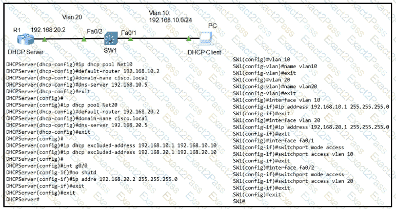
3. Configure R1 as a DHCP server for the network 10.1.3.0/24 in a pool named TEST. Using a single command, exclude addresses 1-10 from the range. Interface Ethernet0/2 on R3 must be issued the IP address of 10.1.3.11 via DHCP.

4. Configure SSH connectivity from R1 to R3, while excluding access via other remote connection protocols. Access for user root and password Cisco must be set on router R3 using RSA and 1024 bits. Verify connectivity using an SSH session from router R1 using a destination address of 10.1.3.11. Do NOT modify console access or line numbers to accomplish this task.

Question # 197

Drag and drop the TCP or UDP details from the left onto their corresponding protocols on the right.

Question # 198

What is a similarity between 1000BASE-LX and 1000BASE-T standards?

A.

Both use the same data-link header and trailer formats

B.

Both cable types support RJ-45 connectors

C.

Both cable types support Rj-45 connectors

D.

Both support up to 550 meters between nodes

Question # 199

Refer to the exhibit.

Between which zones do wireless users expect to experience intermittent connectivity?

A.

between zones 1 and 2

B.

between zones 2 and 5

C.

between zones 3 and 4

D.

between zones 3 and 6

Question # 200

Refer to the exhibit.

An engineer is configuring the HO router. Which IPv6 address configuration must be applied to the router Fa0/1 interface for the router to assign a unique 64-brt IPv6 address to Itself?

A.

ipv6 address 2001:DB8:0:1:C601:42FF:FE0F:7/64

B.

ipv6 address 2001:DB8:0:1:C601:42FE:800F:7/64

C.

ipv6 address 2001 :DB8:0:1:FFFF:C601:420F:7/64

D.

iov6 address 2001 :DB8:0:1:FE80:C601:420F:7/64

Go to page: